Week 9 [Fri, Oct 8th] - Topics
Guidance for the item(s) below:
Previously, you learned about class and object diagrams. Let's touch on another variant of class diagrams that complements the first two. The good news is that it is simply a subset of the notation that you already know.
Can explain object oriented domain models
The analysis process for identifying objects and object classes is recognized as one of the most difficult areas of object-oriented development. --Ian Sommerville, in the book Software Engineering
Class diagrams can also be used to model objects in the the relevant information that needs to be examined to understand a problemproblem domain (i.e. to model how objects actually interact in the real world, before emulating them in the solution). Class diagrams that are used to model the problem domain are called conceptual class diagrams or OO domain models (OODMs).
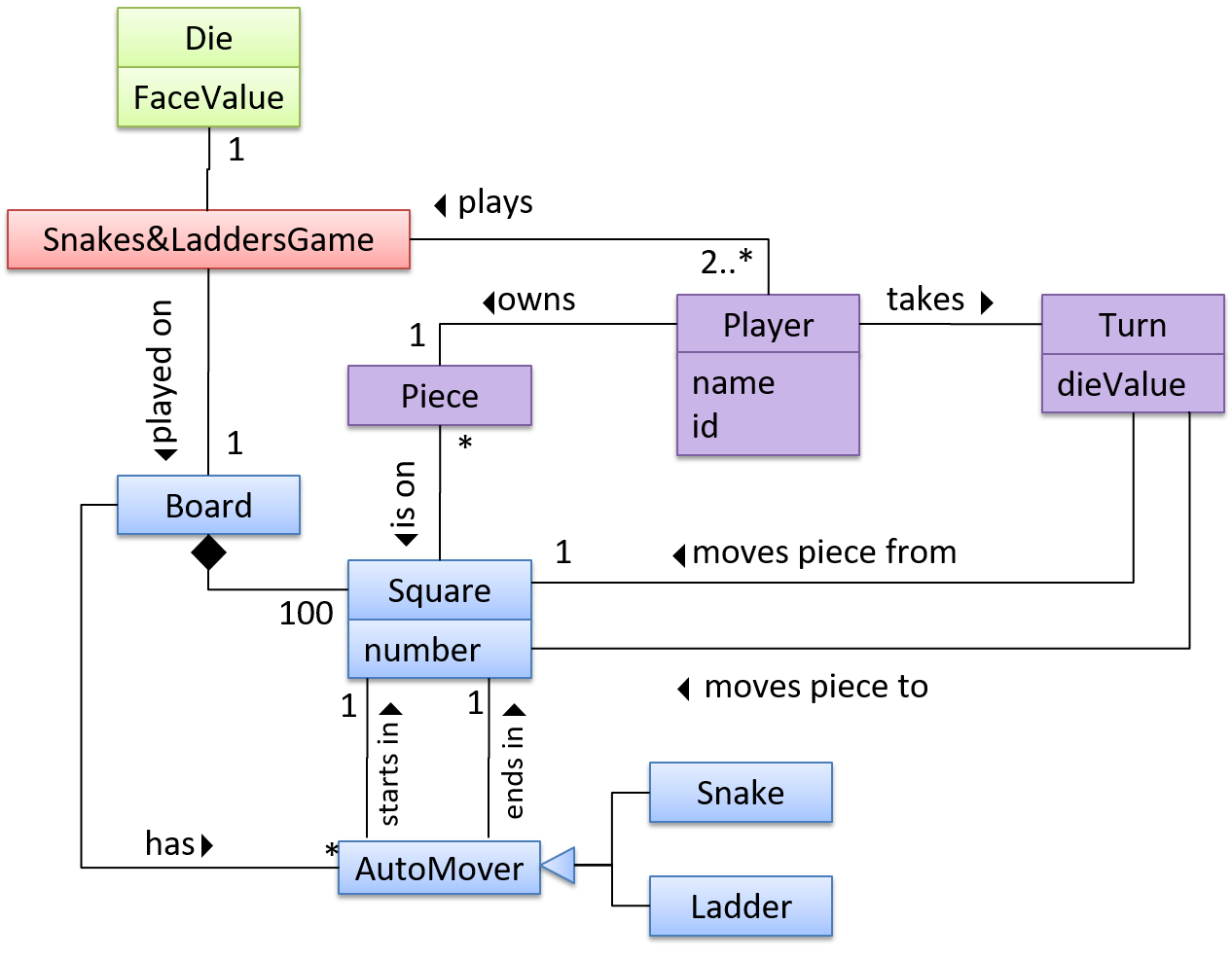
The OO domain model of a snakes and ladders game is given below.
Description: The snakes and ladders game is played by two or more players using a board and a die. The board has 100 squares marked 1 to 100. Each player owns one piece. Players take turns to throw the die and advance their piece by the number of squares they earned from the die throw. The board has a number of snakes. If a player’s piece lands on a square with a snake head, the piece is automatically moved to the square containing the snake’s tail. Similarly, a piece can automatically move from a ladder foot to the ladder top. The player whose piece is the first to reach the 100th square wins.
OODMs do not contain solution-specific classes (i.e. classes that are used in the solution domain but do not exist in the problem domain). For example, a class called DatabaseConnection could appear in a class diagram but not usually in an OO domain model because DatabaseConnection is something related to a software solution but not an entity in the problem domain.
OODMs represents the class structure of the problem domain and not their behavior, just like class diagrams. To show behavior, use other diagrams such as sequence diagrams.
OODM notation is similar to class diagram notation but omit methods and navigability.
Follow up notes for the item(s) above:
Here is an example that shows the steps of drawing an OODM to match a given problem domain.
Guidance for the item(s) below:
Activity diagrams is the last UML diagram type you'll be learning in this module, and probably the easiest and most intuitive of the lot. You've heard about 'flow charts', right? Well, this is the UML equivalent of that.
Follow up notes for the item(s) above:
Here are some examples showing the steps of drawing an activity diagram to match a given workflow.
Guidance for the item(s) below:
A few weeks ago, you learned how to interpret UML diagrams. More recently, you learned how to draw diagrams to match code. There's a third use of models: as an aid for coming up with a design before the code is written.
While this module doesn't ask you to come up with detailed designs before writing code (i.e., our approach leans closer to the agile design rather than the full design upfront approach), this third use of models come in handy at times. Let's learn a bit about that too.
Can explain how modeling can be used before implementation
You can use models to analyze and design software before you start coding.
Suppose you are planning to implement a simple minesweeper game that has a text based UI and a GUI. Given below is a possible OOP design for the game.

Before jumping into coding, you may want to find out things such as,
- Is this class structure able to produce the behavior you want?
- What API should each class have?
- Do you need more classes?
To answer these questions, you can analyze how the objects of these classes will interact with each other to produce the behavior you want.
Can use simple class diagrams and sequence diagrams to model an OO solution
As mentioned in [ Design → Modeling → Modeling a Solution → Introduction], this is the Minesweeper design you have come up with so far. Our objective is to analyze, evaluate, and refine that design.
Let us start by modeling a sample interaction between the person playing the game and the TextUi object.
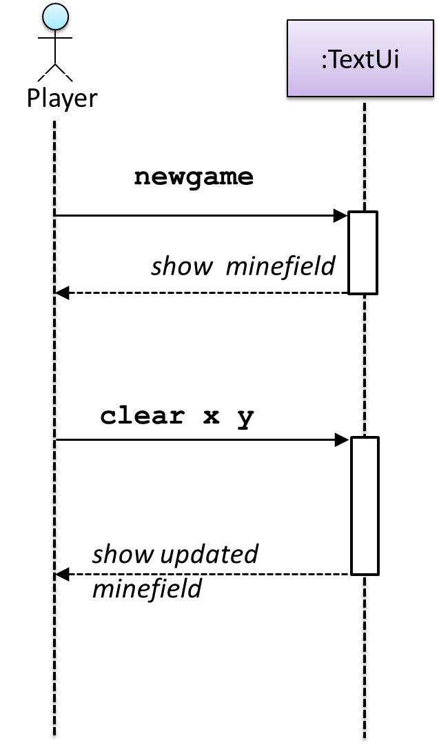
newgame and clear x y represent commands typed by the Player on the TextUi.
How does the TextUi object carry out the requests it has received from the player? It would need to interact with other objects of the system. Because the Logic class is the one that controls the game logic, the TextUi needs to collaborate with Logic to fulfill the newgame request. Let us extend the model to capture that interaction.
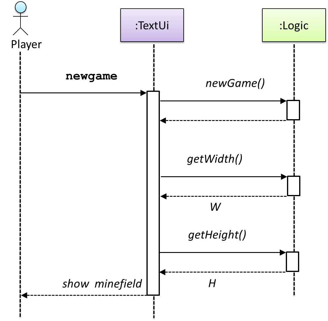
W = Width of the minefield; H = Height of the minefield
The above diagram assumes that W and H are the only information TextUi requires to display the minefield to the Player. Note that there could be other ways of doing this.
The Logic methods you conceptualized in our modeling so far are:
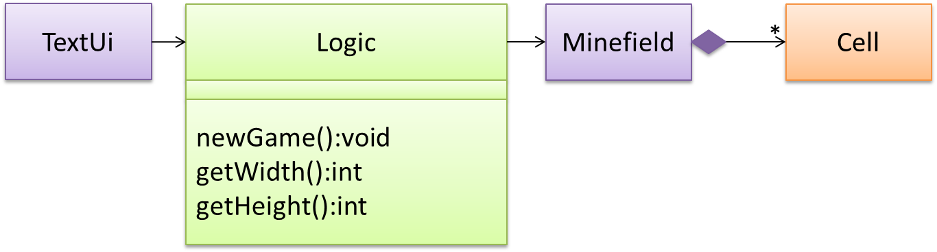
Now, let us look at what other objects and interactions are needed to support the newGame() operation. It is likely that a new Minefield object is created when the newGame() method is called.
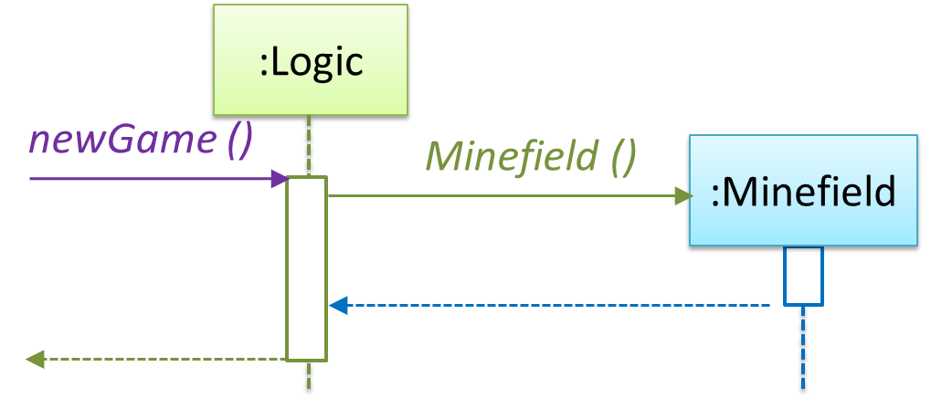
Note that the behavior of the Minefield constructor has been abstracted away. It can be designed at a later stage.
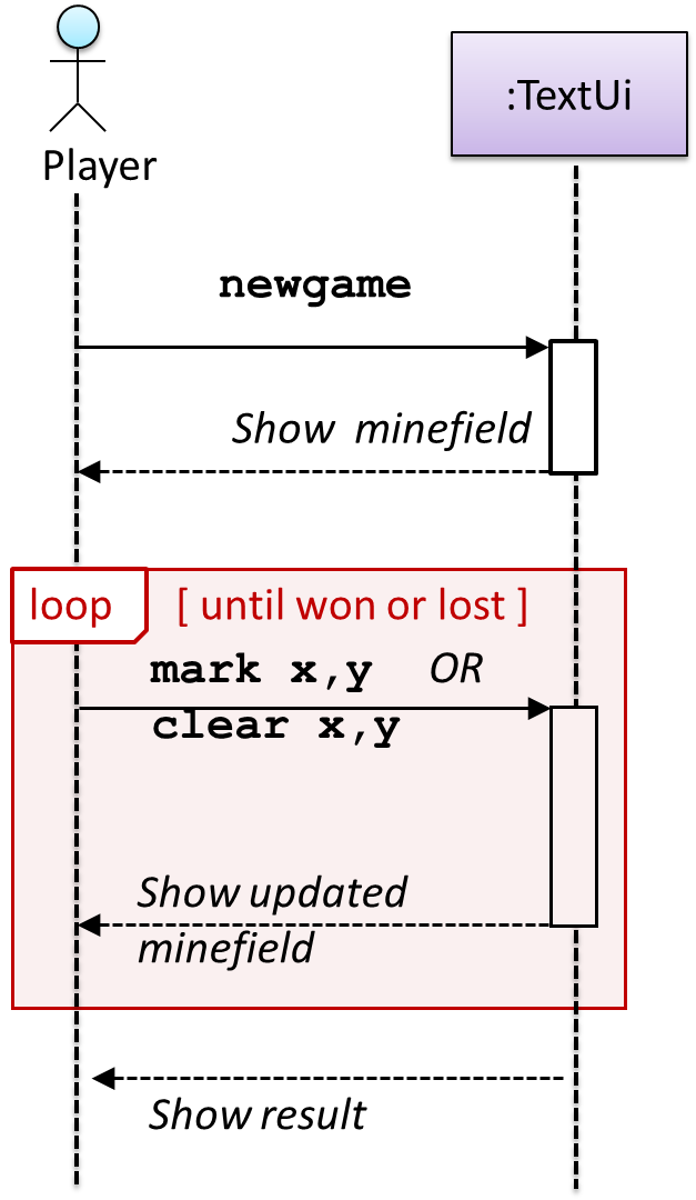
Given below are the interactions between the player and the TextUi for the whole game.
Note that using sequence diagramsa similar technique can be used when discovering/defining the architecture-level APIs.
Defining the architecture-level APIs for a small Tic-Tac-Toe game:
Guidance for the item(s) below:
You've already encountered architecture diagrams in your tP. Pretty soon, you might have to update that diagram to match your new product. Given below are just a brief note about drawing architecture diagrams.
Can draw an architecture diagram
While architecture diagrams have no standard notation, try to follow these basic guidelines when drawing them.
Minimize the variety of symbols. If the symbols you choose do not have widely-understood meanings e.g. A drum symbol is widely-understood as representing a database, explain their meaning.
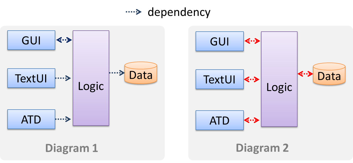
Avoid the indiscriminate use of double-headed arrows to show interactions between components.
Consider the two architecture diagrams of the same software given below. Because Diagram 2 uses double-headed arrows, the important fact that GUI has a bidirectional dependency with the Logic component is no longer captured.
Guidance for the item(s) below:
These principles build on top of the design fundamentals you learned earlier (i.e., abstraction, coupling, cohesion).
Can explain Liskov Substitution Principle
Liskov substitution principle (LSP): Derived classes must be substitutable for their base classes. -- proposed by Barbara Liskov
LSP sounds the same as substitutability but it goes beyond substitutability; LSP implies that a subclass should not be more restrictive than the behavior specified by the superclass. As you know, Java has language support for substitutability. However, if LSP is not followed, substituting a subclass object for a superclass object can break the functionality of the code.
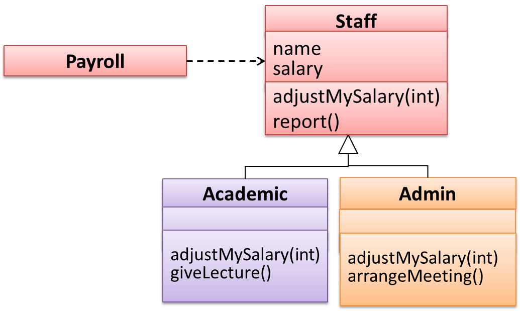
Suppose the Payroll class depends on the adjustMySalary(int percent) method of the Staff class. Furthermore, the Staff class states that the adjustMySalary method will work for all positive percent values. Both the Admin and Academic classes override the adjustMySalary method.
Now consider the following:
- The
Admin#adjustMySalarymethod works for both negative and positive percent values. - The
Academic#adjustMySalarymethod works for percent values1..100only.
In the above scenario,
- The
Adminclass follows LSP because it fulfillsPayroll’s expectation ofStaffobjects (i.e. it works for all positive values). SubstitutingAdminobjects forStaffobjects will not break thePayrollclass functionality. - The
Academicclass violates LSP because it will not work for percent values over100as expected by thePayrollclass. SubstitutingAcademicobjects forStaffobjects can potentially break thePayrollclass functionality.
Can explain open-closed principle (OCP)
The Open-Closed Principle aims to make a code entity easy to adapt and reuse without needing to modify the code entity itself.
Open-closed principle (OCP): A module should be open for extension but closed for modification. That is, modules should be written so that they can be extended, without requiring them to be modified. -- proposed by Bertrand Meyer
In object-oriented programming, OCP can be achieved in various ways. This often requires separating the specification (i.e. interface) of a module from its implementation.
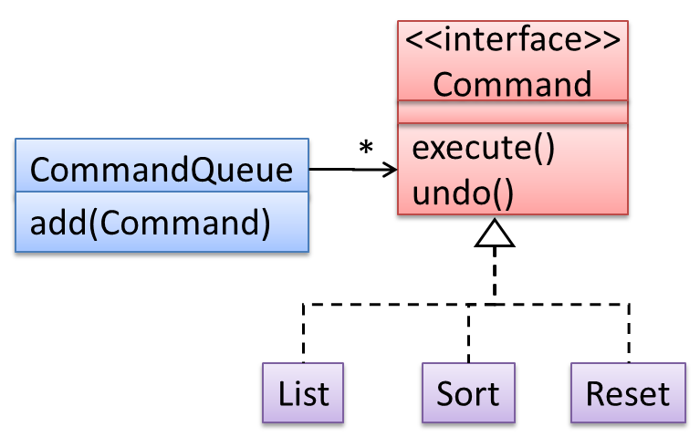
In the design given below, the behavior of the CommandQueue class can be altered by adding more concrete Command subclasses. For example, by including a Delete class alongside List, Sort, and Reset, the CommandQueue can now perform delete commands without modifying its code at all. That is, its behavior was extended without having to modify its code. Hence, it is open to extensions, but closed to modification.
The behavior of a Java generic class can be altered by passing it a different class as a parameter. In the code below, the ArrayList class behaves as a container of Students in one instance and as a container of Admin objects in the other instance, without having to change its code. That is, the behavior of the ArrayList class is extended without modifying its code.
ArrayList students = new ArrayList<Student>();
ArrayList admins = new ArrayList<Admin>();
Guidance for the item(s) below:
If you liked the principles covered above, given below are a few more widely used principles most of which are optional in this module (they were moved to the optional topics in order to reduce the module workload).
The only examinable thing is the term SOLID principles.
Guidance for the item(s) below:
Remember these three topics that we covered early in the module?
Can explain sequential process models
The sequential model, also called the waterfall model, models software development as a linear process, in which the project is seen as progressing steadily in one direction through the development stages. The name waterfall stems from how the model is drawn to look like a waterfall (see below).
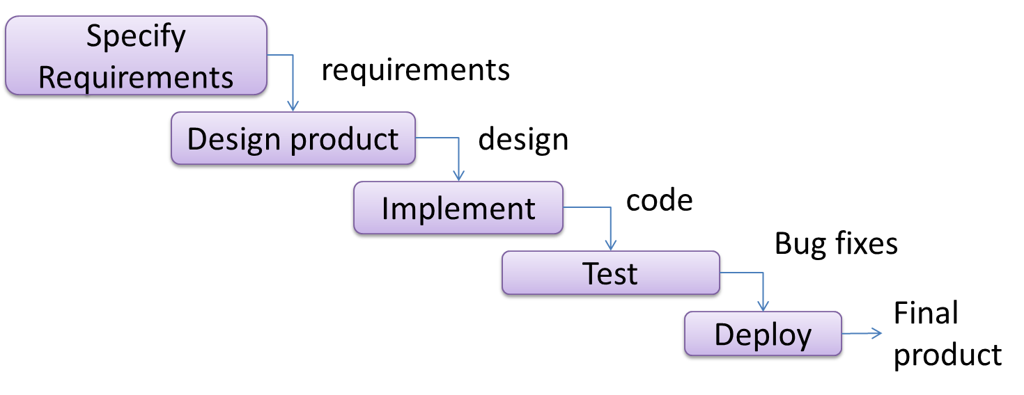
When one stage of the process is completed, it should produce some artifacts to be used in the next stage. For example, upon completion of the requirements stage, a comprehensive list of requirements is produced that will see no further modifications. A strict application of the sequential model would require each stage to be completed before starting the next.
This could be a useful model when the problem statement is well-understood and stable. In such cases, using the sequential model should result in a timely and systematic development effort, provided that all goes well. As each stage has a well-defined outcome, the progress of the project can be tracked with relative ease.
The major problem with this model is that the requirements of a real-world project are rarely well-understood at the beginning and keep changing over time. One reason for this is that users are generally not aware of how a software application can be used without prior experience in using a similar application.
Can explain iterative process models
The iterative model (sometimes called iterative and incremental) advocates having several iterations of SDLC. Each of the iterations could potentially go through all the development stages, from requirements gathering to testing & deployment. Roughly, it appears to be similar to several cycles of the sequential model.
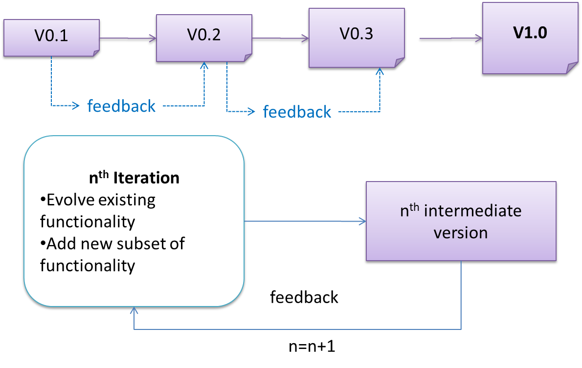
In this model, each of the iterations produces a new version of the product. Feedback on the new version can then be fed to the next iteration. Taking the Minesweeper game as an example, the iterative model will deliver a fully playable version from the early iterations. However, the first iteration will have primitive functionality, for example, a clumsy text based UI, fixed board size, limited randomization, etc. These functionalities will then be improved in later releases.
The iterative model can take a breadth-first or a depth-first approach to iteration planning.
- breadth-first: an iteration evolves all major components in parallel e.g., add a new feature fully, or enhance an existing feature.
- depth-first: an iteration focuses on fleshing out only some components e.g., update the backend to support a new feature that will be added in a future iteration.
Most projects use a mixture of breadth-first and depth-first iterations i.e., an iteration can contain some breadth-first work as well as some depth-first work.
Guidance for the item(s) below:
Let's continue that thread to learn about some SDLC process models that are commonly used in the industry.
Can explain scrum
This description of Scrum was adapted from Wikipedia [retrieved on 18/10/2011], emphasis added:
Scrum is a process skeleton that contains sets of practices and predefined roles. The main roles in Scrum are:
- The Scrum Master, who maintains the processes (typically in lieu of a project manager)
- The Product Owner, who represents the stakeholders and the business
- The Team, a cross-functional group who do the actual analysis, design, implementation, testing, etc.
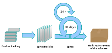
A Scrum project is divided into iterations called Sprints. A sprint is the basic unit of development in Scrum. Sprints tend to last between one week and one month, and are a timeboxed (i.e. restricted to a specific duration) effort of a constant length.
Each sprint is preceded by a planning meeting, where the tasks for the sprint are identified and an estimated commitment for the sprint goal is made, and followed by a review or retrospective meeting, where the progress is reviewed and lessons for the next sprint are identified.
During each sprint, the team creates a potentially deliverable product increment (for example, working and tested software). The set of features that go into a sprint come from the product backlog, which is a prioritized set of high level requirements of work to be done. Which backlog items go into the sprint is determined during the sprint planning meeting. During this meeting, the Product Owner informs the team of the items in the product backlog that he or she wants completed. The team then determines how much of this they can commit to complete during the next sprint, and records this in the sprint backlog. During a sprint, no one is allowed to change the sprint backlog, which means that the requirements are frozen for that sprint. Development is timeboxed such that the sprint must end on time; if requirements are not completed for any reason they are left out and returned to the product backlog. After a sprint is completed, the team demonstrates the use of the software.
Scrum enables the creation of self-organizing teams by encouraging co-location of all team members, and verbal communication between all team members and disciplines in the project.
A key principle of Scrum is its recognition that during a project the customers can change their minds about what they want and need (often called requirements churn), and that unpredicted challenges cannot be easily addressed in a traditional predictive or planned manner. As such, Scrum adopts an empirical approach—accepting that the problem cannot be fully understood or defined, focusing instead on maximizing the team’s ability to deliver quickly and respond to emerging requirements.
Daily Scrum is another key scrum practice. The description below was adapted from https://www.mountaingoatsoftware.com (emphasis added):
In Scrum, on each day of a sprint, the team holds a daily scrum meeting called the "daily scrum.” Meetings are typically held in the same location and at the same time each day. Ideally, a daily scrum meeting is held in the morning, as it helps set the context for the coming day's work. These scrum meetings are strictly time-boxed to 15 minutes. This keeps the discussion brisk but relevant.
...
During the daily scrum, each team member answers the following three questions:
- What did you do yesterday?
- What will you do today?
- Are there any impediments in your way?
...
The daily scrum meeting is not used as a problem-solving or issue resolution meeting. Issues that are raised are taken offline and usually dealt with by the relevant subgroup immediately after the meeting.
Can explain XP
The following description was adapted from the XP home page, emphasis added:
Extreme Programming (XP) stresses customer satisfaction. Instead of delivering everything you could possibly want on some date far in the future, this process delivers the software you need as you need it.
XP aims to empower developers to confidently respond to changing customer requirements, even late in the life cycle.
XP emphasizes teamwork. Managers, customers, and developers are all equal partners in a collaborative team. XP implements a simple, yet effective environment enabling teams to become highly productive. The team self-organizes around the problem to solve it as efficiently as possible.
XP aims to improve a software project in five essential ways: communication, simplicity, feedback, respect, and courage. Extreme Programmers constantly communicate with their customers and fellow programmers. They keep their design simple and clean. They get feedback by testing their software starting on day one. Every small success deepens their respect for the unique contributions of each and every team member. With this foundation, Extreme Programmers are able to courageously respond to changing requirements and technology.
XP has a set of simple rules. XP is a lot like a jig saw puzzle with many small pieces. Individually the pieces make no sense, but when combined together a complete picture can be seen. This flow chart shows how Extreme Programming's rules work together.
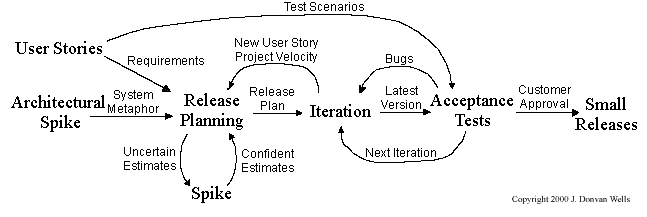
Pair programming, CRC cards, project velocity, and standup meetings are some interesting topics related to XP. Refer to extremeprogramming.org to find out more about XP.
Guidance for the item(s) below:
As you will be updating documentation of your project soon, here are some guidelines to help you with that.